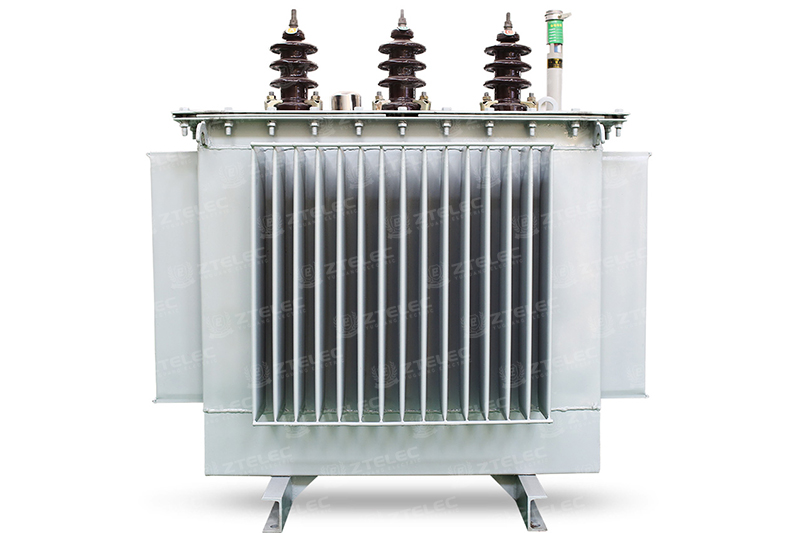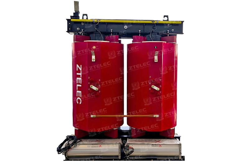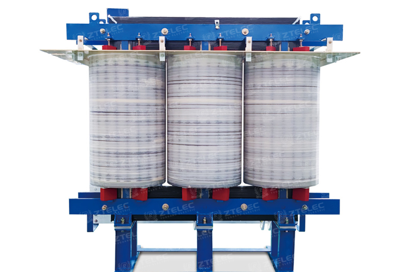

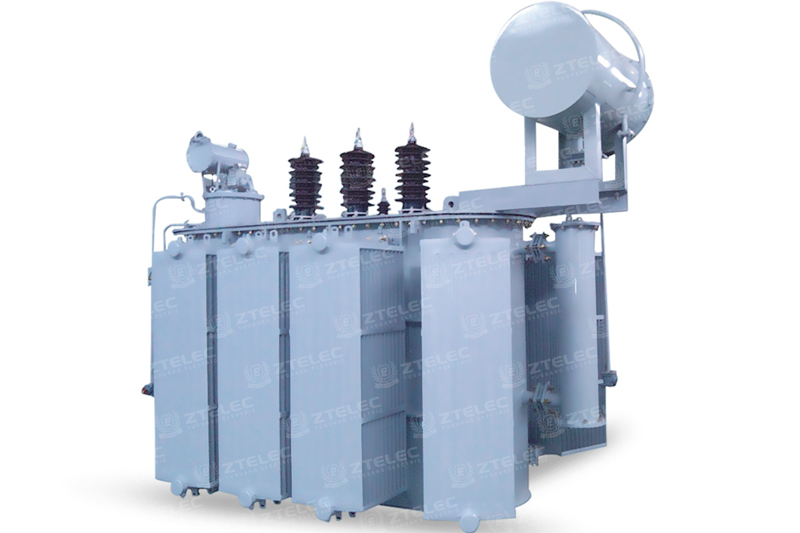
10kV, 20kV and 35kV on-load tap changing voltage regulating transformers that adjust output voltage under live load, improving voltage qualification rate, reactive power compensation, and energy efficiency.
| Rated voltage | 35kV-38.5kV |
|---|---|
| Rated capacity | 630kVA -31.5MVA |
| Application scenarios | Power distribution places such as industrial and mining enterprises, agriculture, and civil buildings, as well as places with a lot of oil pollution and chemical substances in the petroleum and chemical industries. |
| Certifications & Standards | TÜV -issued CE • CB IEC EN ISO 9001• 14001• 45001 |
Voltage on any power line isn't a fixed, unchanging value. As load on the user side rises and falls throughout the day, and as the wider system voltage fluctuates, the actual voltage delivered to the end user shifts along with it. An on-load tap changing transformer is built specifically to correct for this — adjusting its winding taps while the transformer stays energized and connected to load, without any interruption to power supply. This is what separates it from a standard off-circuit tap changer, which can only be adjusted after the transformer is de-energized.
Every transformer has some internal impedance, which means a certain amount of voltage drop is unavoidable during transmission, and that drop changes as the connected load changes. Combine this with normal fluctuations in system voltage, and the result is a voltage swing at the delivery point that can drift outside acceptable limits if left uncorrected. An on-load tap changing transformer monitors this and, once the fluctuation crosses a preset threshold, shifts its tap position after a short delay to bring voltage back into a stable range — all while the load stays connected and power keeps flowing.
This function matters most in power transformers positioned close to the load center. On the primary side, these units typically connect either to the main transmission network at 220kV and above, or to a regional distribution grid in the 35kV to 110kV range, and from there supply both active and reactive power to the load. Because these transformers usually carry a fairly large short-circuit impedance, any change in regional load has a direct effect on the supply bus voltage. Without on-load tap changing capability, that bus voltage would simply follow the load up and down. With it, and working alongside reactive compensation equipment such as parallel capacitors and low-voltage reactors, the transformer can continuously adjust its taps to hold voltage quality within the required range, regardless of how the regional load shifts.
Voltage qualification rate — the percentage of time voltage stays within its rated tolerance band — is one of the core benchmarks used to judge power supply quality. Because an on-load tap changing transformer can correct voltage in real time without taking the line out of service, it keeps this rate consistently high, supporting the steady voltage that both households and industrial or agricultural operations depend on.
Capacitor banks used for reactive compensation have an output that scales with the square of operating voltage, which makes them highly sensitive to voltage changes. When system voltage drops, their compensation effect weakens noticeably. When voltage climbs instead, an uncorrected system risks over-compensating connected equipment, pushing terminal voltage above safe limits and putting insulation and equipment life at risk. An on-load tap changing transformer prevents this cycle. By adjusting the main transformer's tap position promptly to bring bus voltage back into range, it removes the need to shut down reactive compensation equipment to avoid sending reactive power back into the system — protecting both equipment and the value of the reactive compensation investment.
Power loss across a distribution network is minimized when operating voltage stays close to its rated value — deviations in either direction increase losses. Using an on-load tap changer to keep substation bus voltage within its qualified range, so that connected equipment consistently runs near rated voltage, remains one of the most cost-effective ways to reduce ongoing transmission losses across a network.
This series is available across 10kV, 20kV, and 35kV voltage classes, covering the range most commonly required in regional substations, industrial distribution networks, and medium-voltage feeder applications. Selecting the right class depends on the upstream supply voltage at your site and the downstream load profile, and our engineering team can help match the correct voltage class and tap range to your specific network conditions.
These transformers are commonly deployed in regional distribution substations where load fluctuates significantly through the day, industrial facilities with variable or heavy-duty electrical loads, and any network location where voltage stability is required without accepting the downtime that comes with off-circuit tap changing. They're also frequently paired with reactive power compensation systems, since the two work together to maintain both voltage quality and reactive balance across the network.
Reliable on-load voltage regulation depends on tap changer mechanism quality, insulation design, and how well the unit is built to handle repeated switching operations over its service life without degradation. This series is manufactured with these long-term operating demands in mind, giving network operators a dependable way to hold voltage quality steady, protect reactive compensation equipment, and reduce distribution losses — without interrupting supply to the loads that depend on it.
| Rated capacity (kVA) | Voltagegroup | Vectorgroup | Loss (W) | No-load current(%) | Impedance voltage (%) | Boundary dimension (L×W×H,mm) | Weight(kg) | ||
| HV(kV) | LV (kV) | No-loadloss(W) | Loadloss(W) | ||||||
| 2000 | 35- 38.5 | 6.3 10.5 | Yd11 | 2300 | 19200 | 0.50 | 6.5 | 2460×2050×2500 | 2610 |
| 2500 | 2720 | 20600 | 0.50 | 2340×2300×2930 | 3310 | ||||
| 3150 | 35- 38.5 | 6.3 10.5 | 3230 | 24700 | 0.50 | 7.0 | 2350×2350×2990 | 3580 | |
| 4000 | 3870 | 29100 | 0.50 | 2400×2410×3050 | 3990 | ||||
| 5000 | 4640 | 34200 | 0.50 | 2440×2450×3100 | 4740 | ||||
| 6300 | 5630 | 36700 | 0.50 | 8.0 | 2470×2510×3170 | 5120 | |||
| 8000 | 35- 38.5 | 6.3 6.6 10.5 11 | YNd11 | 7870 | 40600 | 0.40 | 2500×2590×3230 | 5880 | |
| 10000 | 9280 | 48000 | 0.40 | 2550×2610×3250 | 7770 | ||||
| 12500 | 10940 | 56800 | 0.35 | 8.0 | 2780×2660×3300 | 8750 | |||
| 16000 | 13160 | 70300 | 0.35 | 3020×2710×3370 | 9930 | ||||
| 20000 | 15560 | 82700 | 0.30 | 3250×2760×3410 | 12760 | ||||
| Rated capacity (kVA) | Voltagegroup | Vectorgroup | Loss (W) | No-load current(%) | Impedance voltage (%) | Boundary dimension (L×W×H,mm) | Weight(kg) | ||
| HV(kV) | LV (kV) | No-loadloss(W) | Loadloss(W) | ||||||
| 2000 | 35- 38.5 | 6.3 10.5 | Yd11 | 2300 | 19200 | 0.50 | 6.5 | 2460×2050×2500 | 2610 |
| 2500 | 2720 | 20600 | 0.50 | 2340×2300×2930 | 3310 | ||||
| 3150 | 35- 38.5 | 6.3 10.5 | 3230 | 24700 | 0.50 | 7.0 | 2350×2350×2990 | 3580 | |
| 4000 | 3870 | 29100 | 0.50 | 2400×2410×3050 | 3990 | ||||
| 5000 | 4640 | 34200 | 0.50 | 2440×2450×3100 | 4740 | ||||
| 6300 | 5630 | 36700 | 0.50 | 8.0 | 2470×2510×3170 | 5120 | |||
| 8000 | 35- 38.5 | 6.3 6.6 10.5 11 | YNd11 | 7870 | 40600 | 0.40 | 2500×2590×3230 | 5880 | |
| 10000 | 9280 | 48000 | 0.40 | 2550×2610×3250 | 7770 | ||||
| 12500 | 10940 | 56800 | 0.35 | 8.0 | 2780×2660×3300 | 8750 | |||
| 16000 | 13160 | 70300 | 0.35 | 3020×2710×3370 | 9930 | ||||
| 20000 | 15560 | 82700 | 0.30 | 3250×2760×3410 | 12760 | ||||

ZTELEC Yuguang Electric Technology, founded in 2014, builds on state-owned industrial expertise to deliver reliable power solutions worldwide.
Copyright © 2026.ztygelectric All rights reserved.